My eurorack case has an ES-9 module, which can function as an audio interface, mixer, and MIDI/CV bridge. It has pins on the back for hooking up input and output MIDI jacks. I've attached a TRS jack to the input pins, brought it around to the front, and can now send MIDI commands over it.
Expert Sleepers provides a web-based interface that can run offline in a single page and connect to the ES-9 over Web USB. The design is unintuitive, but very powerful once you understand it. All the same, for simple use it's a bit much. Others have created their own simplified web interfaces for basic mixer-only uses. In theory, one could connect a tablet to the ES-9 via USB-OTG and then use that to control the ES-9. I did try this myself; I don't remember why I chose not to go in this direction, frankly. Maybe because I don't have a tablet and am stuck using a tiny phone screen, or maybe because my phone had trouble connecting. If I remember, I'll have to give it another go and update this page...
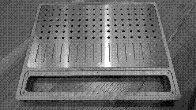
I have some scrap plywood from other projects lying around, as well as a couple microcontroller boards. This often gets me into trouble, and this time was no exception. I've gone from "I'm just going to rig something small and simple up with a couple potentiometers for panning and volume on the channels I use most" to "I'm making a 16 channel 'bludgeoning mixer' with a 45mmm slider, two toggle switches, and four knobs per channel, plus cutouts for touch-sensitive control interfaces for when I'm using this as a desktop synthesizer or sequencer."
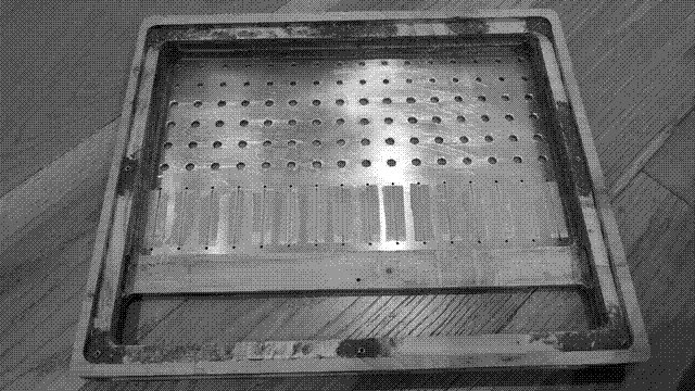
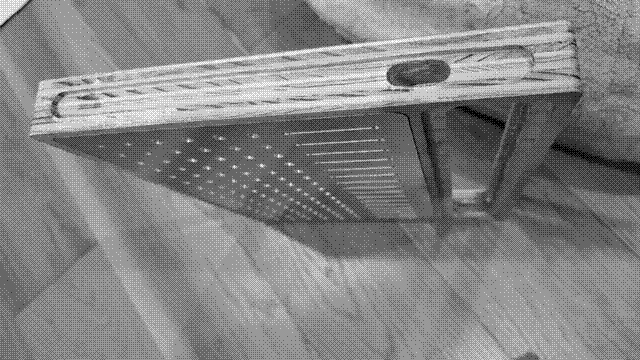
At any rate, I've been reading data sheets and memos on capacitive touch sensors the past few days, made a few false starts toward designs, made a complete design I had to scrap because the touch sensor IC I'd chosen, the AT42QT2120, appeared to have a hardwired 16ms keyscan interval limit. I began again with the MSP430FR2676, which advertises a minimum 1ms keyscan interval, achieved by scanning up to four channels in parallel. It was limited to 16 capacitive touch channels, which meant I was going to have to bring in a second controller to get all the keys I wanted on the front panel (which I imagined would result in severe noise/interference problems), or else reduce my electrode count.
In a Reddit thread on the subject, I found someone suggest looking at the ARM MCUs in response to a post pondering the MSP430 series for touch control. Following that line of inquiry quickly lead me to the RA2E1 and RA2L1 MCUs from Renasas, which allow all RX lines to be scanned in parallel and which can have up to 32 touch sensitive channels. With the 64 pin LQFP or QFN packages, I get 30 channels, but since I'll be using the SPI interface that drops down to 26 channels. More than plenty for the number of buttons and sliders I want on the faceplate!
I've got an evaluation board for the RA2E1 ordered (only $13!), so now I've got to start designing a test board for possible electrodes. I need to find a good balance between latency, sensitivity, and expressiveness. I'd like to have capacitive aftertouch without having to resort to covering the electrodes with a silicon mat.